ATSF Howard Branch
LED Marker Lamps
Click
for larger images
Updated 1-20-10, more photos to come.
Click on photos for enlargements.
Model railroaders are used to working lights on their locomotives, but few have ventured into marker lights on their cabooses. One of the problems has been making good track-caboose contact to constant lighting. With 603 LEDs, this is no longer a problem. Below is my way of lighting cabooses.
|
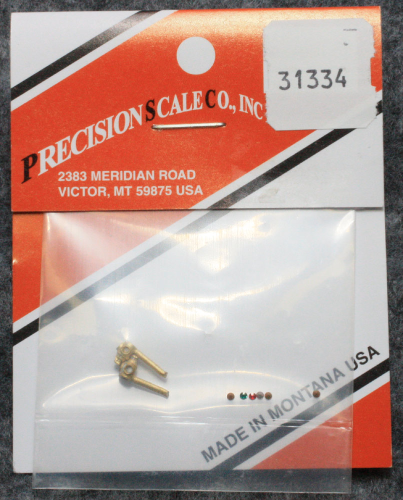
Modeling the Santa Fe, no one
makes (to my knowledge) a good representation of a Santa Fe marker light.
Instead, I began with a Precison Scale brass 31334
marker. |
|
|
The first revision is to allow the insertion of a 603 LED.
If you are unfamiliar with these, you can get them from Richmond Controls, prewired. Be
sure to specify that you want them wired for "ditch lights." This means
both wires are soldered to come out on the same side of the LED. Use Red
Insulating Varnish to coat the back so that your brass marker will not short
out the LED. Here is a video of
wiring 603s. |
|
|
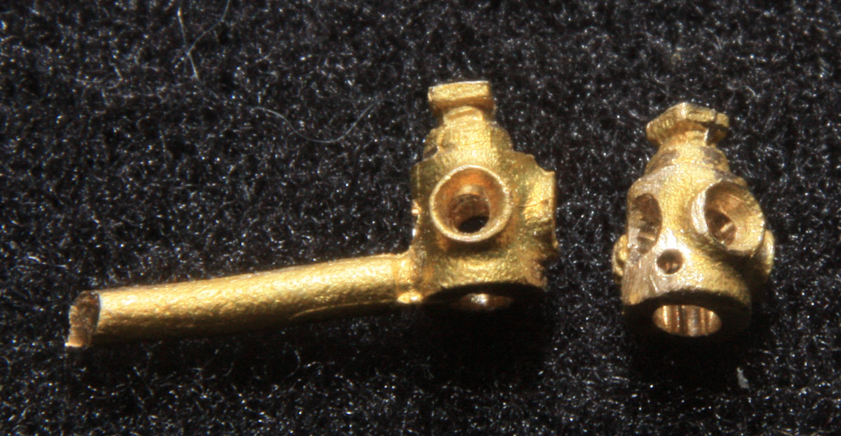
Take a #56 or 55 drill and drill out in inside of the marker lamp from the bottom. I use the drill in a single speed Dremel tool with a sewing machine foot control to get the speed slow enough for this work. I use pliars with smooth jaws to hold the marker without leaving grip marks. Use tape around the drill bit as a depth gauge to insure that you don't drill too far. Then use a #70 drill to drill out the lens backs. Since the Santa Fe used markers with 4 lenses, and the precision scale only has three, drill one through and out the back. Cut off the brass tab that would otherwise be used to mount the marker. File the back smooth so that the marker is round. If you plan to mount the marker to your caboose with a piece of piano wire, drill an appropriate size hole in the marker at a 45 degree angle to the normal light beam directions. Finally, use that #55 drill to countersink the extra lens you added to the marker. |
|
|
You are now ready to insert the 603 LED. To make it easy to allign it, connect it to a 3V power source so the light is illuminated while you do this proceedure. The next product you need is Pacer Formula 560 Canopy Cement. It is used by model airplane folks, looks like Elmers, and dries clear. Squirt it inside the marker. Then insert the LED so that the back of the LED is toward the mounting hole you drilled (the 45 degree hole). Turn the LED slightly to that you get light out of all 4 lenses. Now sit it down and let the glue dry for a few minutes. |
|
|
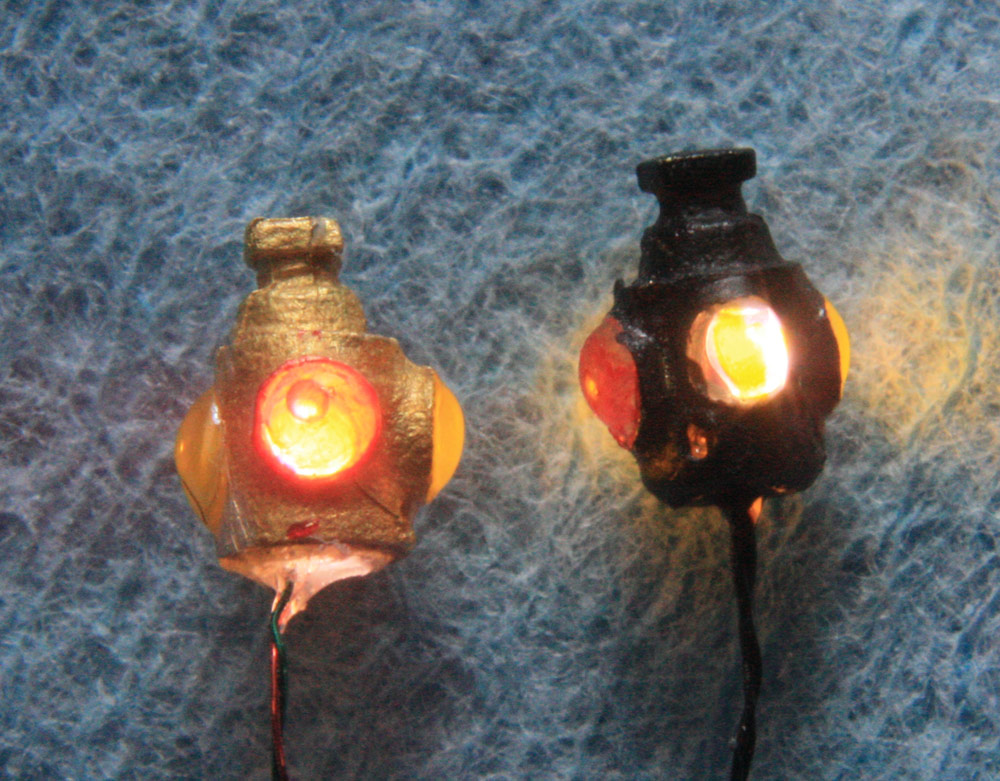
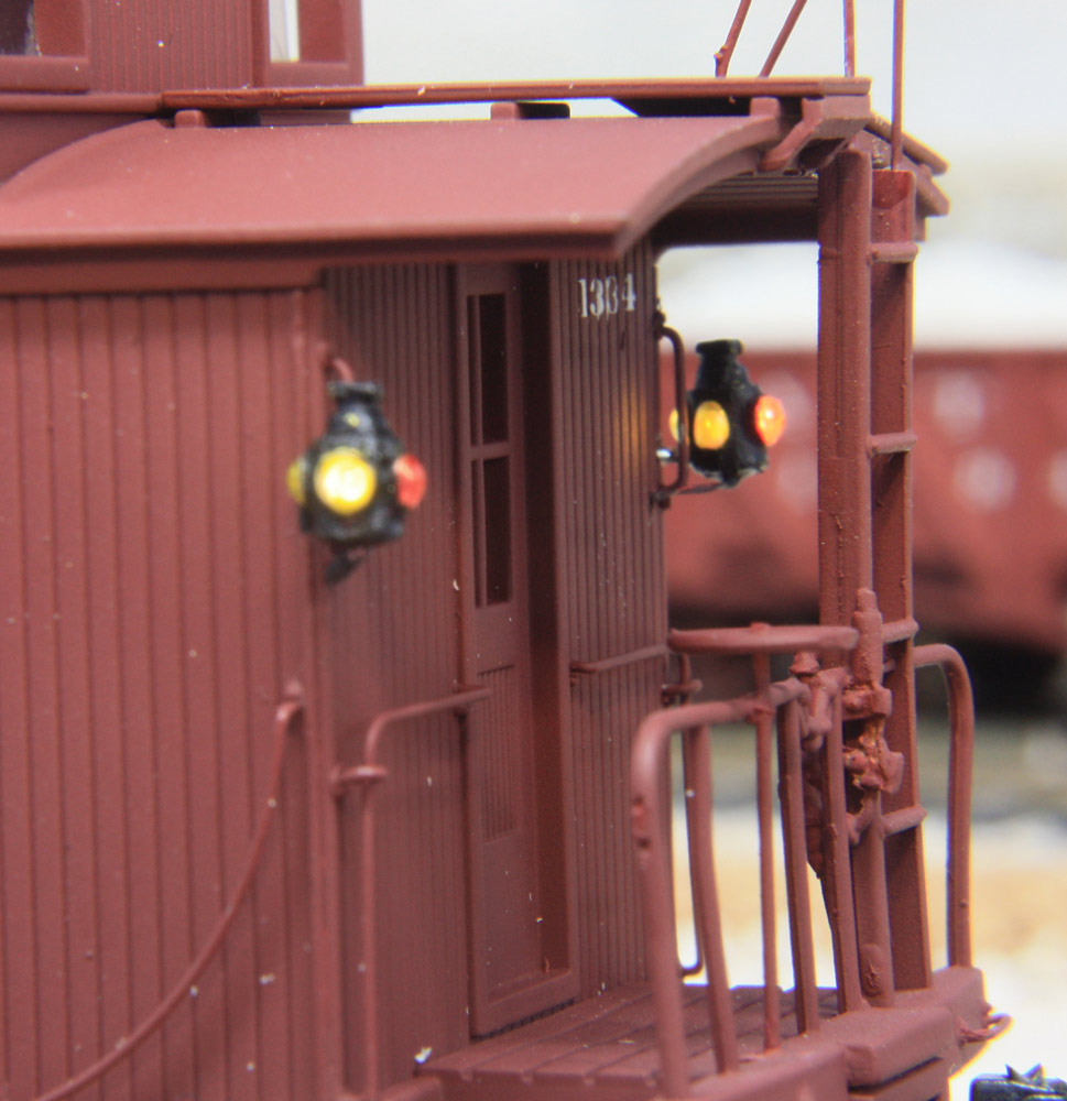
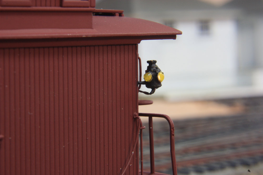
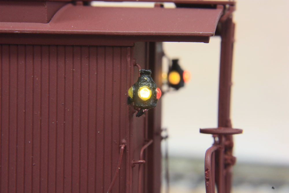
Now use a drop of Gallery Glass (Hobby Lobby, Window Color by Plaid Enterprises) to make the lenses. Ruby Red (16015) and Sunny Yellow (16004) are good for ATSF purposes. The lenses pictures here were made with my previous method which was not as good. You are now ready to paint the marker black. In ATSF case, the rear is red, the others are amber. |
|
|
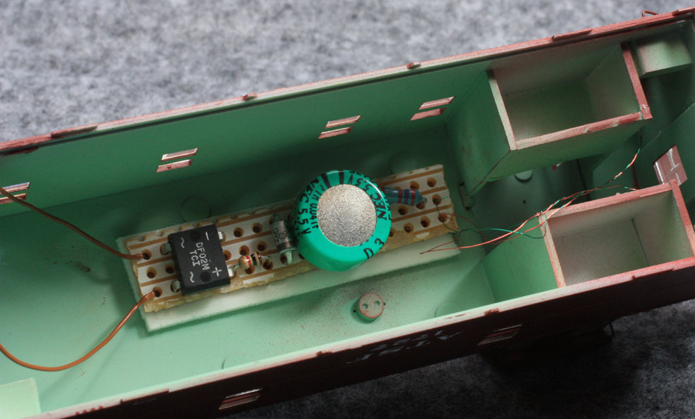
Now for the power supply. The beauty of the LED is that
they use almost no power. Therefore a simple circuit
with a capacitory can power the LEDs even after the
car is removed from the track. Once the capacitor is charged, going over
unpowered frogs or dirty track will not cause the least bit of flicker. The
LEDs are wired in parallel. |
|
|
I use both a commercial circuit available from Richmond Controls, and a homemade circuit designed by modeler Jim Betz.. Miniatronics also has a circuit. The homemade circuit pictured cost less than $3. NEC no loner makes this super cap but any 5.5V or larger super cap will work. |
|
|
I cut a piece of piano wire into an "L" shape
and drill an appropriate hole in the marker lamp
mounting location at a 45 degree angle to the
caboose walls. One leg of the "L" is interted
through the hole from the inside and glued with ACC. |
|
|
Drill #80 holes in the back wall of your caboose to let the wires inside the body, then solder them to the circuit and mount it to the roof of the caboose with double sided foam tape. |
|
|
For power pickup, I use Intermountain wheelsets in plastic
trucks. The "H" shaped wipers come from Richmond Controls
(EZ61-WPRS), though you can do similar pickup with phosphor bronze wire.
Remember, you don't have to have perfect power
pickup for this to operate. The 2/56 screw which holds the truck on goes
through the floor to the inside of the body of the caboose where power wires
are attached to the circuit board. |
|
|
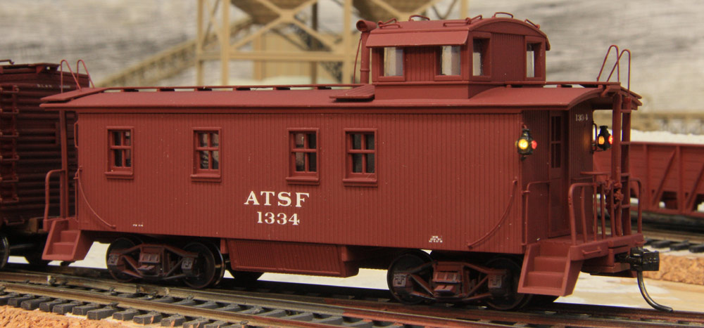
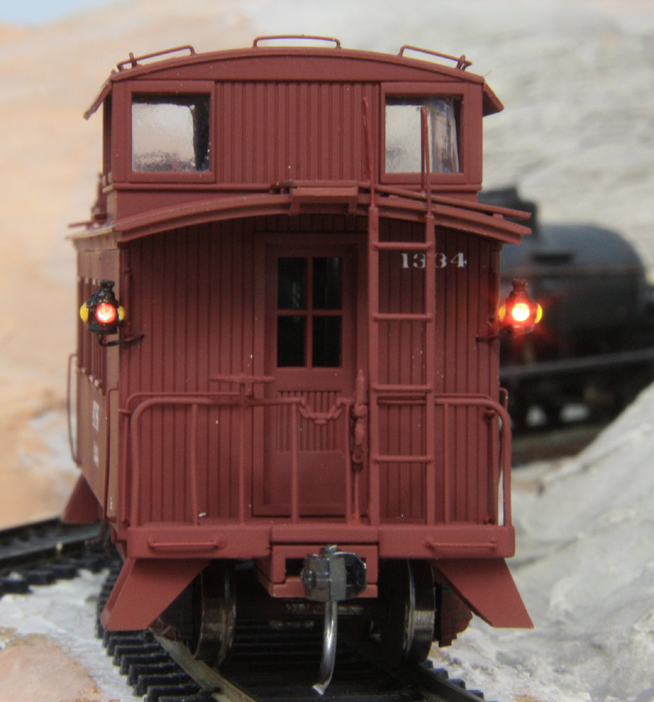
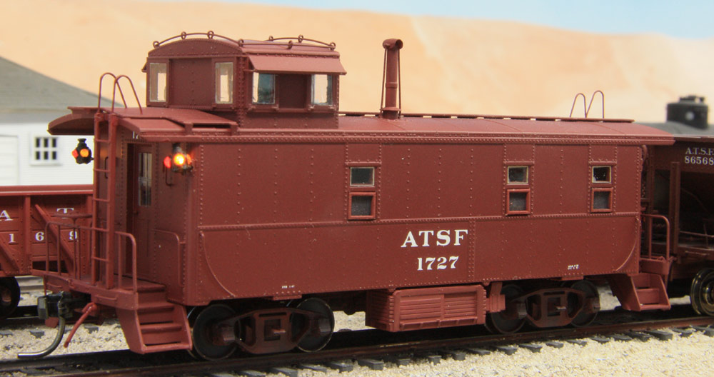
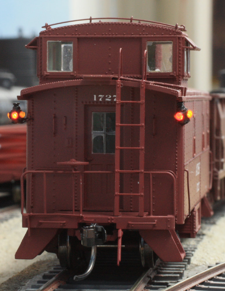
Finally
I include some finished product photos. These are on a Walther's wood side
ATSF caboose and Intermountain Santa Fe kit. |
|
|
|
|
|
|
|