ATSF Howard Branch
Electromagnetic Uncouplers
12-4-06
Materials List:
- #26 Magnet Wire. 1/4 pound (4 oz.) spools are common at about $5. If you have a lot to do, purchase a 10 pound spool from Kelvin.com for about $65 delivered. Small magnets require 1.5 oz, larger ones 2 oz of wire, about 9 uncouplers per pound ($.72 each based on 10 pound spool).
- Scotch #27 Glass Cloth Tape. This will cost about $10 per roll. A roll will do about 50 magnets ($.20 each).
- 2" x 3/16" x 48" steel strap at Home Depot, to make 12 magnets.
- 1/4" x 20 x 1.5" flat head bolts.
- Box of 100 1/4" flat washers, to make 12 magnets.
- Scrap 1/8" plexiglass or other material like Masonite.
- Epoxy glue.
- Total cost: $1.25 each. If done in assembly line fashion, it takes me 3 hours to do 12 magnets once I have all of the supplies in hand.
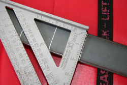 | Mark the steel bar into 2" sections. A fine point paint pen will make a very visible line. |
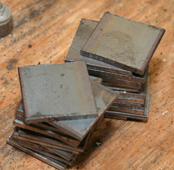 | Use a metal cutting saw to cut the bar into 24 pieces, 2" square. A portable metal cutting band saw will greatly speed the process. Don't worry if the cut sides are not perfectly square. The reference sides will be the sheered sides of the strap, not the cut sides. Use a grinder to remove the burrs and make the corners safe. |
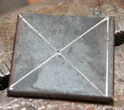 | Use one of the flats as a set up piece. Mark off about 1/8" at a sheered side, then X through the balance to find its center. This will be the drill reference for everything else. |
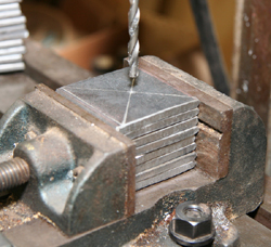 | Place the plates in a machinist's vise on a drill press and aligned the drill to the correct center. Be sure to place the pieces in the vise based on their sheered sides, not the cut sides. Drill half of the sides with a #7 drill, this hole later to be tapped. Drill the other half with a 1/4" drill. The use of cutting oil will speed up the work and save tools. |
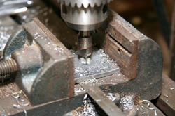 | Take the sides drilled with the 1/4" drill and countersink them to accommodate the 1/4" flat head screw. |
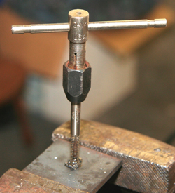 | Tap the other half of the sides with a 1/4" 20 tap. Now clean the grease and oil off of these pieces and do any further deburring that is needed. |
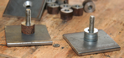 | The core for the magnets can be either of two things. The easiest is to use washers. Put the flat head screw through the countersunk side and then stack washers to a depth of 7/16". About 8 regular washers will work fine. The other route - if you have a lathe - is to turn plugs from 1/2" steel stock to a width of 7/16". Which ever case, be sure to use magnetic material. Stainless steel or aluminum will not work. the core must be solid magnetic steel. Screw the threaded plate on and use a thread locking liquid (Locktite) to make everything secure. Be sure the sheet plates are alligned. |
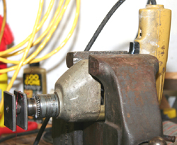 | Place a variable speed drill into a vise to hold it, then chuck the screw into the drill. Winding the coil will now go fast and easy. |
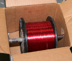 | Put the wire on a shaft in a box below the drill. This makes it easy for the wire to wind off. |
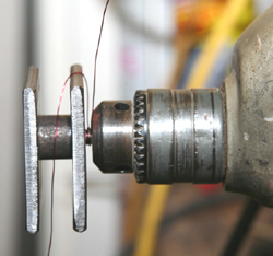 | Start the wire around the metal and then the screw. This does not need to be tight, just enough to hold when you start the drill. Always have the wire leaving the coil on the shortest (bottom) side of the uncoupler. Put on a leather glove and wind the wire through its fingers. This serves as a tensioner when winding the wire around the core. |
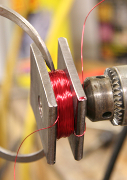 |
Start the drill slowly and spool on wire until the coil is 1.5" in diameter. That is plenty. Putting more wire on the coil will lower amps used by the magnet but will not make it any stronger. Its strength has been maximized by the time it reaches 1.5". With the large plates of steel, heat has not been a problem in 8 years of operations. |
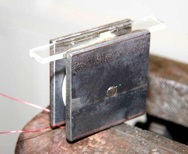
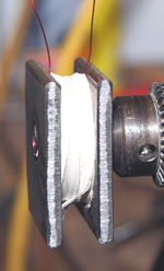 | Now wrap the coil with Scotch 27 Glass Cloth Electrical Tape. This is a high temperature tape. One overlaping wrap is sufficient. Have both wires sticking out of the short side (bottom side) of the magnet. Now test it to make sure it works. Put a piece of flex track between two 4x4 blocks of wood, put a car on top, and hold the magnet below. There is no need to continue work if it does not work, but I have not had a failure. |
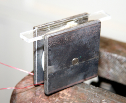 | Assuming it works, cut off the protruding part of the bolt flush with the magnet. Then epoxy a piece of scrap plexiglass (or other material) between the plates on the long side of the magnet. A piece 7/16" wide works perfectly. The magnet is now complete and ready to install. |
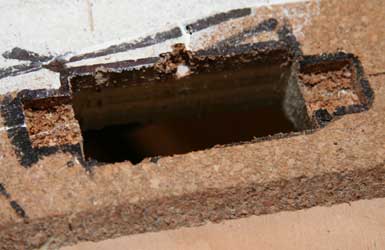 | Installation involves cutting a hole 2" long by 13/16" wide in the center of the roadbed and sub-roadbed. |
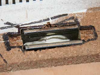 | Remove 1/8" of material to allow the plexiglass mounting tabs to fit flush with the top of the sub roadbed. Apply some adhesive caulk to the sides when the magnet is placed into the hole. It is now very secure. |
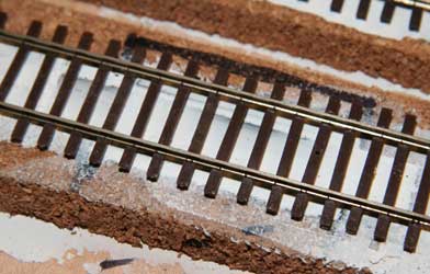 | Lay track over it as normal. Be sure the track is centered over the magnet. |
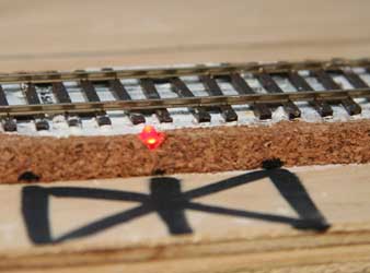 | Drill a hole in the edge of the roadbed aligned with the center of the magnet and install the indicator (see below). Wire it in parallel with the magnet. When the magnet is on, the light is on. As with any LED, the polarity must be right for illumination. If it does not come on with power, reverse the wires. |
Power for these magnets is best at 18V DC with the ability to handle 2 amps. Push buttons used to activiate these must be rated highter than 1 amp.
Indicator
Gil Freitag has installed LED indicators beside each uncoupler. It is wired in parallel with the magnet so that it is on when the uncoupler is on, helping the modeler to know precisely where the hidden ramp is located and reminding him to turn it off before it gets too hot, or worse. These are very simple to produce.
Materials list:
- Small LED (10/$1)
- 1/4 watt resistor, 2200 ohms, +/-5% ($.07 each)
- Heatshrink insulation ($1.50/3')
- Misc wire (stranded wire preferred)
- Total cost: $.25 each.
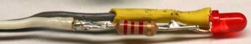
The short lead on the LED is the positive lead. Cut it to about 1/2" and solder a piece of wire to it. Use a heat sink on the LED side of the solder joint and use a 30 watt iron. Too much heat will destory the LED. Now put a piece of heatshrink over it and use the heat from your iron to shrink it down.
Now cut the long lead about 3/4" long. Cut the resister leads to 1/4." solder one end of the resistor to the LED and the other end to another piece of wire. Don't forget a heatsink. I recommend that you standardize your wiring, like a black wire on the LED lead and a white wire on the resistor lead.
You have finished the indicator. Hook it in parallel with your uncoupler. Insert the LED in a hole drilled in the subroadbed centered on the uncoupling ramp.
Use an 18V DC power supply to make it all work. These uncouplers will draw 1.3 amps, so select a suitable transformer.