ATSF Howard Branch
Turnouts
Click
for larger images
Updated 12-16-06
 | My
turnouts are all handlaid, but with two types of ties. Of course some of them
are on wood ties, the conventional method. I don't know what frog size turnouts
these are, as they are whatever is needed for the layout being planned. |
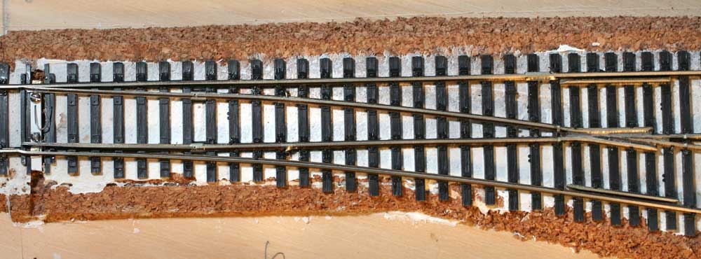 | Most of my turnouts are laid on Central Valley tie blocks. These are available from Central Valley and their distributors in a wide variety of frog sizes, right and lift hand, #4-#9. They are self gauging making life easy. The majority of my turnouts on the branchline are #5 frog size. |
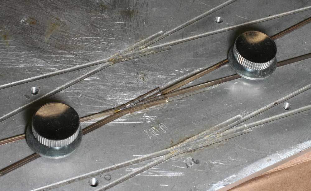 | I made a jig to use in constructing frogs. It consists of an "X" milled in a 1/4" thick plate of aluminum at the angles of 1:4; 1:5, and 1:6. Tapped holes were placed so that thumb screws with washers could be used to hold the 4 necessary rails in place while they were being soldered. The two pointed frog rails were ground in a grinder. If you are making a bunch at the same time - the best way to do it - an angle plate can be clamped to your grinder so that grinding the rail is like putting pencil in a pencil sharpener. For the other rails, I made another jig. I drilled a hole just large enough for rail to fit into it in a small block of metal. The hole depth matches the length of the wing rail. Sticking the raw rail into the hole and then bending it insures that the wing is always the same length. |
 | All of my frogs are insulated, unpowered. Once the turnout is complete, I gap the frog on both end and insert styrene held with CA glue. When it sets, the styrene can be trimmed to match the rail. I attach electric drops to the point rails as well as to the primary rails. |
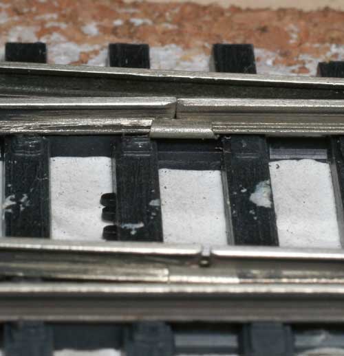 | I am making points in two different ways. Staging tracks have a continuous rail from frog to point. There are probably more stable. However, they don't weather and you can't ballast then in prototypical ways. My visible turnouts use hinged points. The hinges are 1/2 of a normal rail joiner. Dremel cutoff disks are best for cutting them. Everything I have done to this point is in code 70. |
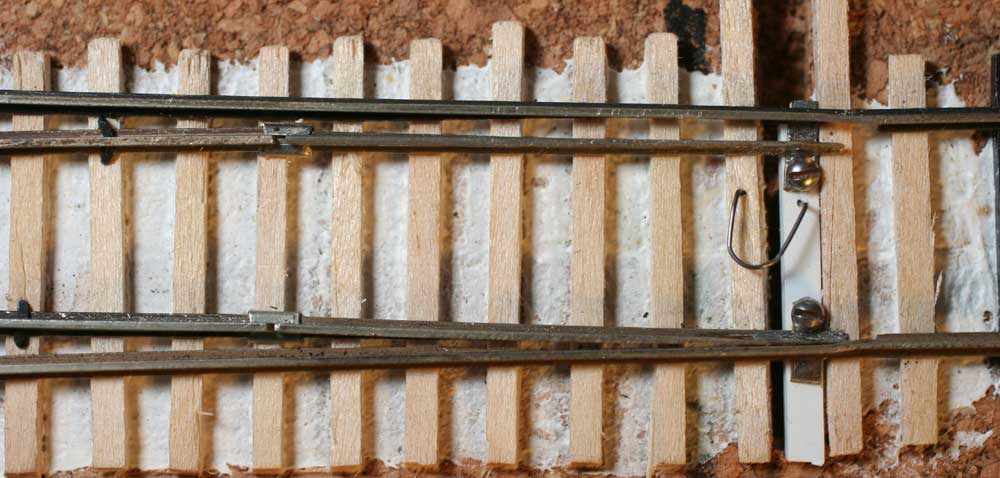 | Hard to reach turnouts on the layout are controlled by switch motors. Accessible turnouts are manual with only a spring to hold them in place. I make these springs out of piano wire. Using the Kadee coupler adjusting pliars, the wire is bent 90 degrees. Such a curved bend is much better than a sharp bend. Then the ends are bend 90 degrees down and inserted in the throw bar and an adjacent tie. Simple, and works fine. It helps if the parts to be inserted are not straight down, but bent slighly away from each other so they won't come out easily. |
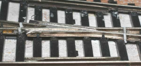
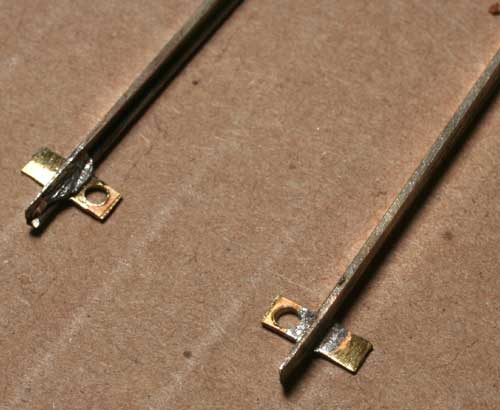 | My points are first ground with a grinder, then finished with a file. The inside of the rail head is filed even with the web so that it comes to a strong point. A piece of .020x.080" brass forms the throw bar connector. It extends long enough to be under the outside rails when the turnout is open or closed. It keeps the rail from rising up and maintains electrical conductivity to that outer rail. The brass is drilled with a #48 drill for a 1-72 screw. I take a piece of brass and drill holes every 1/4" or so. Again, I have created a jig to help do this. Then I tin the whole thing. Finally I cut individual pieces to solder to the bottom of the points. The points are left longer than needed and can be used for any size of turnout. I make up a bunch at a time. When the other rails of the turnout are laid, the point is cut to fit. My throw bar is .080 x .080 styrene. A #53 hole is drilled and 1-72 screw used to attach the point rails. |
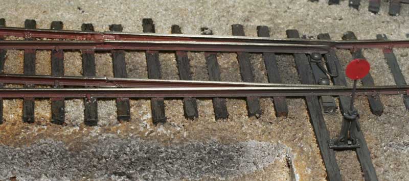 | Now the turnout is complete. Ballast, weather, and enjoy. One benefit of this type of construction is that if in ballasting the points stick, it is easy to unscrew them, remove, and clean the whole area. If points break, simply replace them. |